

The conventional pitch for decorative ceiling beam systems says they do two things, look good and improve the acoustics of the room. The first half is true. The second half is usually misleading. A solid timber beam or a laminate-faced slatted beam with nothing behind it, absorbs almost no sound. Wood is reflective. A flat lacquered timber face sits at roughly αw 0.05 to 0.10 and reflects most of the sound energy hitting it back into the room. If a sales sheet quotes a beam system’s “acoustic performance” without specifying what’s installed in the void above the beam, the number is either marketing or it’s measuring something the buyer is not actually getting.
That’s the gap this piece is about. Where the sound absorption in a slatted ceiling actually happens, how to read the technical data sheet to know whether you’re buying it and the small handful of install choices that decide whether the finished room hits the αw class you specified or sits one class below.
The Absorption Happens in the Backing, not the Wood
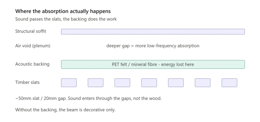
A slatted ceiling beam absorbs sound through a specific mechanical setup. The slats sit at a defined width and gap ratio, often roughly fifty millimetres of wood to twenty millimetres of open space and behind the gaps sits a porous acoustic backing, usually a polyester (PET) felt or a mineral fibre. Sound passes through the gaps, hits the backing and loses energy to the porous material. The slats themselves contribute reflection and a degree of mid-frequency tuning, but the absorption number is overwhelmingly set by what’s behind them.
Vtec’s MAXISLAT ceiling beam system makes this explicit on it’s data sheets. The beams are lightweight slatted units with optional EchoTone acoustic backing, available as 9 mm black or 12 mm coloured PET boards with 60 percent recycled content. Without that backing, the beams are decorative. With it and depending on the configuration chosen from the published set, the system can hit Class C or Class B absorption rated under EN ISO 11654.
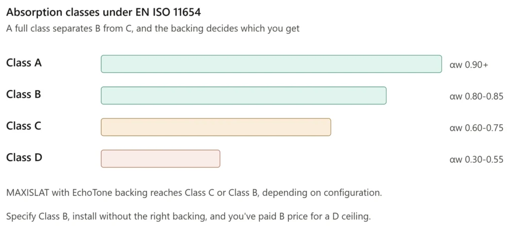
That distinction matters because Class C corresponds to an αw range of 0.60 to 0.75 and Class B to 0.80 to 0.85, a full class apart. A specifier asked to hit Class B in a reception or lecture theatre, who installs the beam without the right backing, has bought a Class D or unclassified ceiling at a Class B price.
Read the Fire and Acoustic Data as Assembly Numbers, not Component Numbers
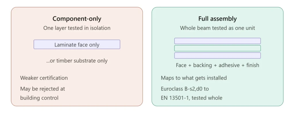
There is a second technical trap and it shows up most often on fire performance, but the same principle applies to acoustic data. A beam system can advertise that it’s components meet Euroclass B-s2,d0 when only the laminate face has been tested or only the timber substrate, not the assembled beam with backing, adhesive and finish layer together.
EN 13501-1 lets you test either way. Vtec publishes assembly testing, the full beam plus backing plus finish, tested as one unit to EN 13501-1 and classified Euroclass B-s2,d0. That’s the only test that maps to what actually gets installed. Component-only certification is weaker and, on a contested project, may be rejected at building control.
For acoustic data, the same logic holds. ISO 354 reverberation room testing measures a specific configuration: the slat profile, the gap width, the backing thickness, the air gap to the soffit above. Change any of those at install and the αw class on the data sheet no longer applies. The number you saw on the brochure was the number for a specific build-up. The number you get in the room is the number for the build-up you actually installed.
The Install Detail That Quietly Costs you a Class
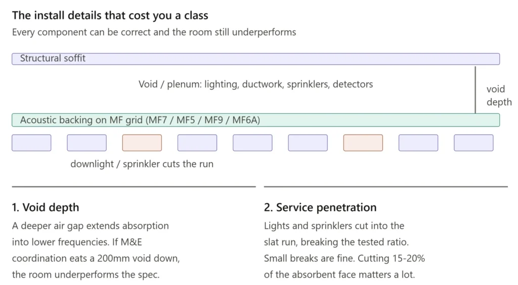
Slatted beam systems hang from the structural soffit, usually on a metal framework. In the UK that’s typically an MF ceiling grid: MF7 primary channels suspended off the soffit on steel angle, MF5 top hats forming the secondary grid and MF9 connecting clips joining the two, with MF6A perimeter channel at the walls. The void between the beams and the soffit, the plenum, is where the lighting, ductwork, sprinklers and detectors sit.
That void depth is part of the acoustic equation. A larger air gap behind a porous absorber extends absorption into lower frequencies. A backing tested at a 50 mm air gap records a different low-frequency curve than the same backing tested tight to the soffit. If the original specification assumed a 200 mm void and the M&E coordination ate into that, the room sounds worse than the αw value on the spec promised, even though every component is correct.
The other quiet cost is service penetration. Lights, sprinkler heads and access panels cut into the run of slats, breaking the slat-to-gap ratio that was tested. Small breaks don’t matter. A reception lobby with recessed downlights cutting through fifteen or twenty percent of the absorbent face matters quite a lot.
What to Check Before you Sign off
A short list, ordered by what most often goes wrong on real projects:
- Ask for the assembly fire certificate, not component certificates. EN 13501-1 testing of the full assembled beam, with finish and backing, classified Euroclass B-s2,d0 or better.
- Ask for the αw value at the specific configuration you are installing, with the named backing thickness and the air gap depth it was tested at. Don’t accept a single advertised “Class A” figure without the build-up it was measured at.
- Confirm the slat-to-gap ratio in your chosen configuration. If services penetrate more than roughly fifteen to twenty percent of the absorbent face, ask the acoustician what the realistic in-room performance becomes.
- For commercial projects under M&E coordination, check the void depth post-coordination, not on the architect’s original section. The drop ceiling level changes during fit-out more often than the acoustic spec gets revisited.
- Check that the manufacturer offers CAD-led integration for lighting and HVAC cut-outs. Cutting on site without the modelling damages the slat regularity and almost always shows visually.
The systems that get this right are unfussy to specify and forgiving to install. The systems that get it wrong are the ones where the buyer pays for the ceiling that was on the brochure and ends up with the ceiling that was on the data sheet’s worst-case row. The difference is not in the wood, it’s in what sits behind it and what the void around it looks like once the services are in.